Networking Models
Overview
Networking models and standards define how hardware and software systems communicate and share information. Key goals include:
- Reliable Communication - Ensure data is sent and received correctly.
- Layered Functions - Separate responsibilities into layers for easier management.
- Packet-Based Transmission - Use packets as the basic unit of communication.
- Standardized Protocols - Consistent routing, addressing, and control mechanisms.
- Layer Extensibility - Allow additional functionality without disrupting core layers.
- Vendor-Neutral and Scalable - Work across different vendors and scale efficiently.
Layers
Most network models have at least two layers:
-
Upper Layer (Host/Application Layer)
- Handles connection integrity and session management.
- Transforms data into a universal format.
- Facilitates application-level communication.
-
Lower Layer (Media/Transport Layer)
- Receives bits from the physical medium
- Converts the received bits into frames.
- Adds routing information to create packets.
- Prepares data for higher layers to process.
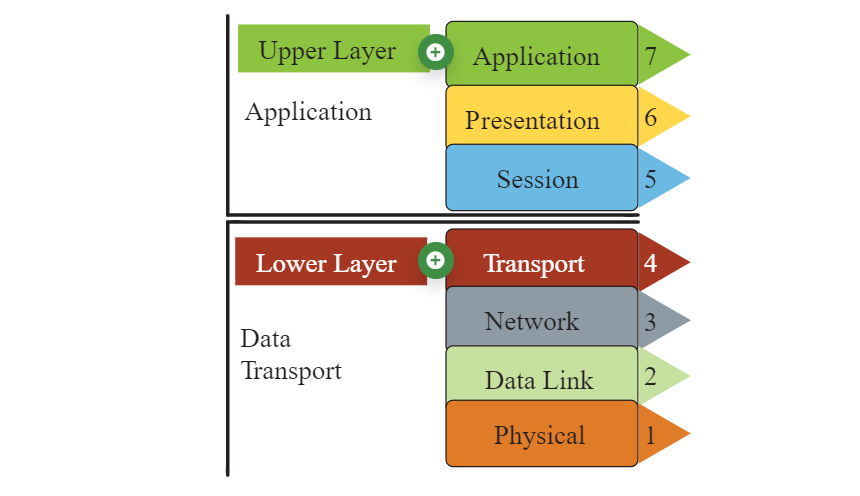
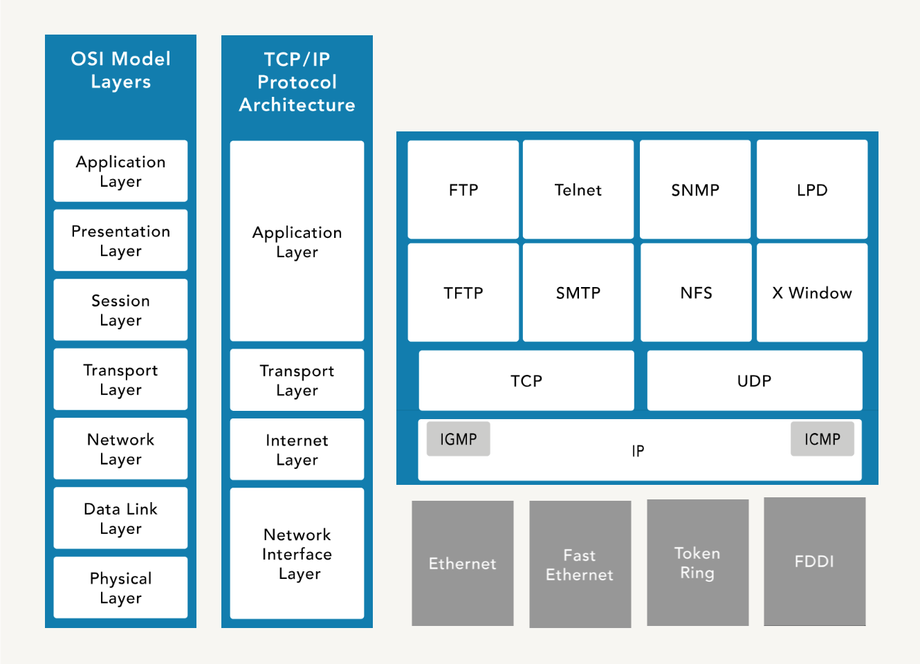
OSI Model
The Open Systems Interconnection (OSI) Model is a conceptual framework for describing the communication structure of interconnected computer systems, which comprises of seven layers.
| No. | OSI Layer | Description / Notes |
|---|---|---|
| 7 | Application |
|
| 6 | Presentation |
|
| 5 | Session |
|
| 4 | Transport |
|
| 3 | Network |
|
| 2 | Data Link |
|
| 1 | Physical |
|
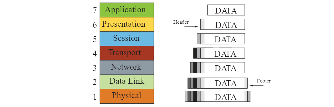
Encapsulation
When data is transmitted over a network, it goes through a process of encapsulation and de-encapsulation.
With encapsulation, data is wrapped with protocol information at each layer as it moves down the OSI model. Each layer adds its own header (and sometimes footer) to the data, which is used for routing, error checking, and delivery. The data is prepared for transmission over the physical medium.
- Data at application layer
- Segment at transport layer
- Packet at network layer
- Frame at data link layer
- Bits at physical layer
The form that a piece of data takes at any layer is called a protocol data unit (PDU). During encapsulation, each succeeding layer encapsulates the PDU that it receives from the layer above in accordance with the protocol being used.
When messages are sent on a network, the encapsulation process works from top to bottom.
De-encapsulation
De-encapsulation occurs at the receiving end, where the data is unpacked as it moves up the layers. Each layer removes its corresponding header/footer and processes the information before passing it to the next layer.
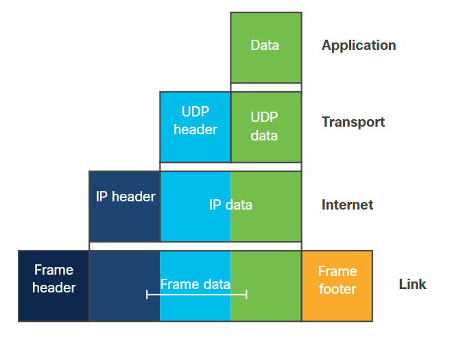
TCP/IP Model
Transmission Control Protocol/Internet Protocol (TCP/IP) is platform-independent but resource-intensive. It is designed for ease of use rather than security. It predates the OSI model.
| No. | TCP/IP Layer | Description / Notes |
|---|---|---|
| 4 | Application Layer |
|
| 3 | Transport Layer |
|
| 2 | Internet Layer |
|
| 1 | Network Access Layer |
|
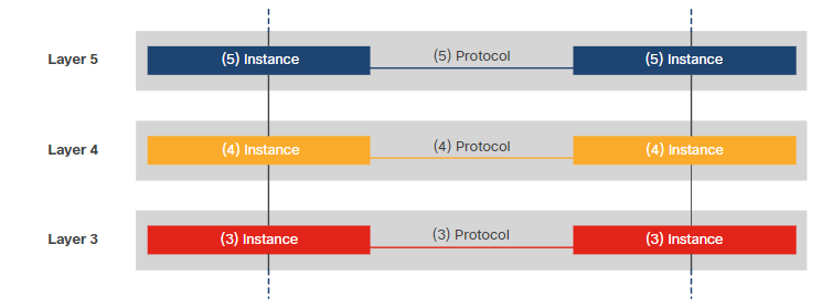
Data Flow in Layered Models
Data moves through layers from the sender to the receiver, with each layer adding or removing headers. End devices follow the full stack of protocols to ensure messages are delivered correctly.
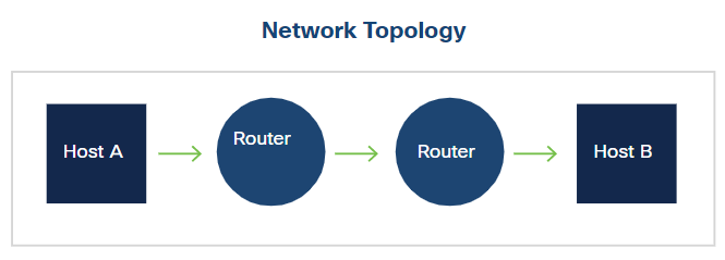
The network access layer (also known "Link"layer) operates at the local network connection to which an end-device is connected. It deals with moving frames from one NIC to another NIC on the same network. Ethernet switches operate at this layer.
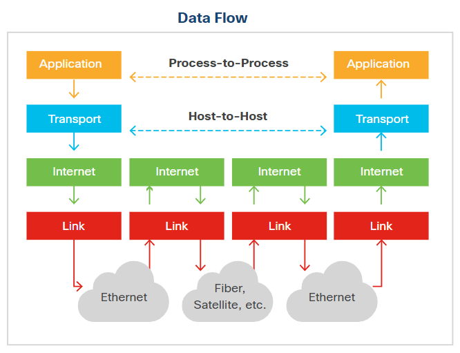
The internet layer sends data across multiple networks, which connects physically separate networks in a process called internetworking. Routers operate at this layer and use routing protocols to forward packets from the source network to the destination network. IP handles addressing and routing in the TCP/IP model.
The layered model ensures that data can travel across local and wide networks reliably, with each layer performing its role in sending, routing, and receiving information.
Transmission Types
Networks can send data in several ways depending on the target:
| Type | Description |
|---|---|
| Unicast | One-to-one communication between a single sender and a single receiver |
| Broadcast | One-to-many communication to all devices on a network segment |
| Multicast | One-to-many communication to a specific group of devices |
| Anycast | One-to-one-of-many communication, delivered to the nearest or best receiver |
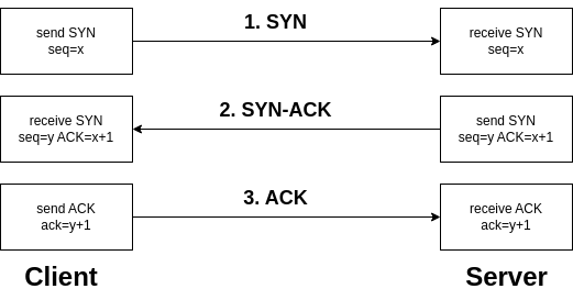
TCP Handshake
The SYN, SYN-ACK, and ACK handshake is a process used in the TCP (Transmission Control Protocol) to establish a connection between two devices on a network.
-
SYN (Synchronize)
- Initiates the connection request.
- The sender indicates its intention to establish a connection.
- The sender picks an initial sequence number.
-
SYN-ACK (Synchronize-Acknowledge)
- Acknowledges the receipt of the SYN packet.
- Indicates acceptance of the connection request.
- The receiver also selects an initial sequence number.
-
ACK (Acknowledge)
- Confirms the acknowledgment of the SYN packet.
- Establishes the connection.
- Data transfer can begin after the ACK is received.
This three-step handshake ensures that both the sender and receiver are ready to exchange data and have agreed upon initial sequence numbers for reliable communication.
UDP
User Datagram Protocol (UDP) is a connectionless protocol that enables fast data transmission without establishing a connection, which makes it suitable for low-latency applications like gaming and streaming.
- Connectionless, reducing overhead but less reliable
- No error checking or data recovery, leaving this to the application
- Lightweight, fast, and efficient for small data transmissions
- Supports broadcasting and multicasting
- Ideal for live broadcasts and conferencing
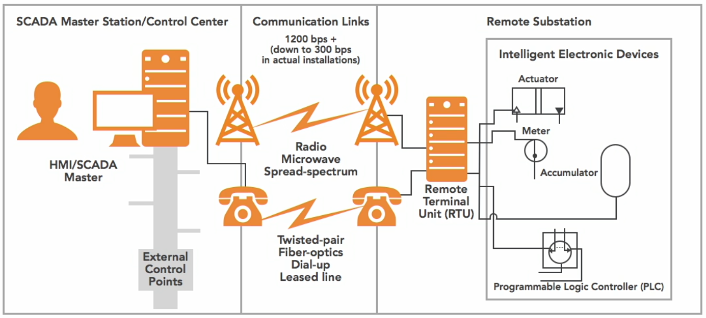
DNP3
Distributed Network Protocol (DNP3) is a multilayer communication protocol primarily used in utility and industrial automation systems to enable reliable and efficient data exchange between control equipment.
- Widely used in SCADA systems for real-0time monitoring and controll
- Robust communication, time-stamped data, and event logging
- Ensure interoperability between different vendors' equipment
How It Works:
- Remote Terminal Unit (RTU)
- The RTU gathers data from sensors or field devices
- Data is sent to the SCADA master station
- Communication Links
- Channels (wired or wireless) that facilitate the exchange of data
- Data is exchanged between RTUs and the SCADA master station.
- SCADA Master Station
- Central system that receives data from RTUs and processes it
- Issues control commands back to the RTUs
- Enables real-time monitoring and control of the entire network.
Diagram:
Circuit-Switched vs Packet-Switched
Circuit-switched is a communication method where a dedicated path is established for the entire session.
- Dedicated path for the duration of the session
- Ensures consistent bandwidth and low delay
- Used in traditional telephone networks
Packet-switched breaks data into packets and sent over shared network paths.
- More efficient use of bandwidth, but has variable delay
- Common in modern IP networks and the Internet
Multiplexing Techniques
Multiplexing is a method of combining multiple signals to share a single communication channel efficiently.
-
Time-Division Multiplexing (TDM)
- Multiple signals share a channel by taking turns in fixed time slots
- Ensures predictable timing and low interference
- Common in digital telephony
-
Statistical Time-Division Multiplexing (STDM)
- Dynamically allocates time slots based on active demand
- More efficient than fixed TDM when traffic is bursty
- Reduces wasted bandwidth
-
Frequency-Division Multiplexing (FDM)
- Each signal occupies a separate frequency band simultaneously
- Common in analog radio and TV transmission
- Requires filters to avoid overlap between bands
-
Wavelength-Division Multiplexing (WDM)
- Optical fiber variant of FDM using multiple light wavelengths
- Increases fiber capacity without laying more cables
- Used in long-distance and high-speed networks
Bit Rate Categories
Bit rate categories define how much data is transmitted per unit time and the guarantees provided by the network.
-
CBR (Constant Bit Rate)
- Connection-oriented, fixed throughput
- Suitable for voice/video applications that need consistent delivery
- Predictable performance with low latency
-
UBR (Unspecified Bit Rate)
- Connectionless, no guaranteed throughput
- Best for non-critical applications like file transfers
- No reserved bandwidth, may experience variable delay
-
VBR (Variable Bit Rate)
- Connection-oriented, throughput varies depending on traffic
- Balances efficiency and service quality
- Good for applications tolerant to delays
- Example uses: Email or web browsing
-
ABR (Available Bit Rate)
- Connection-oriented
- Dynamically adjusts throughput based on network load
- Ensures fair bandwidth allocation among users
- Useful in shared networks where traffic fluctuates
Session Layer Communication Modes
The session layer defines how two applications communicate over a network.
-
Simplex
- Communication flows in one direction only
- Rare in practice; mostly used for broadcasting or sensors
-
Half-Duplex
- Two-way communication, but only one side sends at a time
- Example: walkie-talkies
-
Full-Duplex
- Two-way communication simultaneously
- Example: telephone conversations, Ethernet networks
SNMP
Simple Network Management Protocol (SNMP) is used to monitor and manage network devices.
- Tracks device status, performance, and alerts
- Consists of a manager (central server) and agents (network devices)
- Enables network administrators to maintain health, configure devices, and respond to issues