Network Cabling
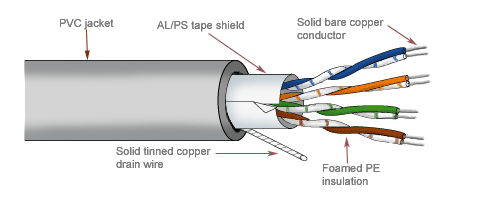
Coaxial Cabling
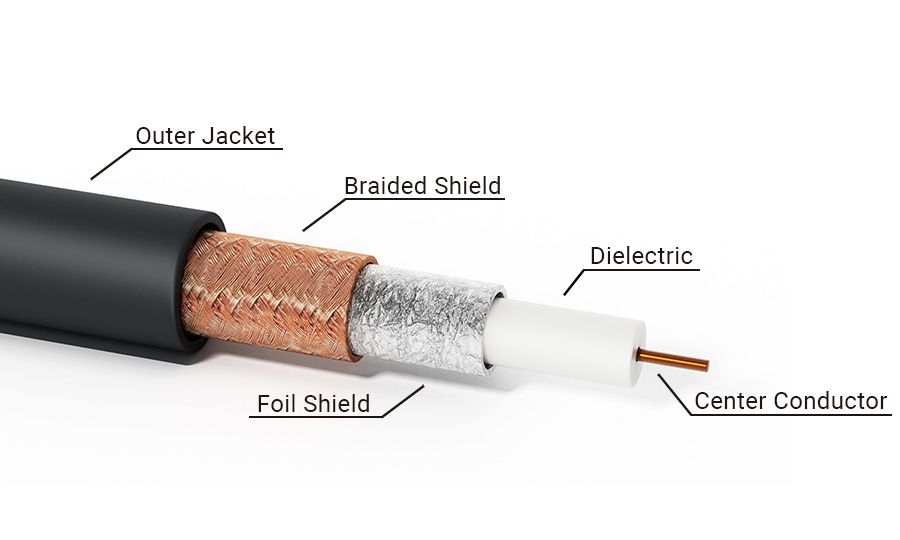
Coaxial cabling is a type of electrical cable used primarily in radio frequency (RF) communications, television, and satellite systems. It is known for its superior performance in high-frequency signal transmission compared to twisted-pair cables.
- Higher performance than twisted-pair cables, used in RF communication.
- Shielded and commonly used for cable television and satellite.
- More resistant to interference and signal degradation over long distances.
Characteristics
Coaxial cables offer specific characteristics that make them suitable for certain environments where resistance to electromagnetic interference (EMI) and radio frequency interference (RFI) is critical.
- More resistant to EMI and RFI than twisted-pair.
- More expensive than twisted-pair but allows for longer Ethernet segments.
- Copper core carries multiple analog signals, also known as broadband.
- Can transmit greater bandwidth and over longer distances than twisted-pair.
Types of Coax Cables
-
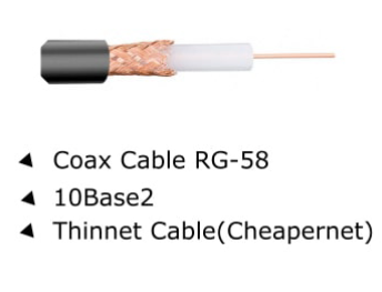
Thinnet
-
Flexible, used for short-distance Ethernet networks
-
Easy to install but prone to damage
-
-
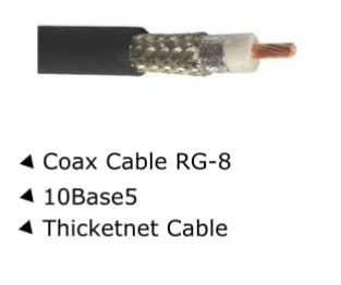
Thicknet
-
Rigid and durable, used for long-distance Ethernet networks
-
More difficult to install but offers higher data capacity
-
-
Broadband Coax
- Used for data, TV, and Internet services
- Supports multiple signals simultaneously
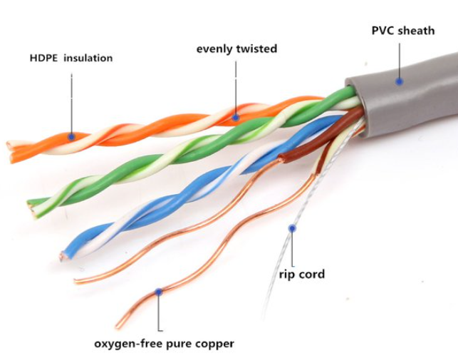
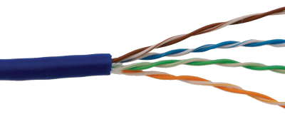
Twisted-pair Cabling
Twisted-pair cabling is the most commonly used medium for local area networks (LANs), especially Ethernet CAT 5E. It is cost-effective and widely used in residential and commercial networking.
Types of Twisted-pair Cables
-
Shielded Twisted-pair (STP)
-
Extra shielding for protection against interference
-
Used in industrial settings with higher EMI
-
-
Unshielded Twisted-pair (UTP)
-
Lacks additional shielding, making it cheaper and easier to install
-
Most common in home and office networks
-
CAT Ratings
| UTP Category | Characteristics | Usage |
|---|---|---|
| CAT 1 | Supports voice transmission only | Telephone communications |
| CAT 3 | Supports up to 10 Mbps | Early Ethernet networks, telephony |
| CAT 4 | Supports up to 16 Mbps | Token Ring networks (rarely used now) |
| CAT 5 | Supports up to 100 Mbps | Older Ethernet networks, phased out |
| CAT 5E | Supports up to 1 Gbps | Standard for modern Ethernet networks |
| CAT 6 | Supports up to 10 Gbps over short distances | Used in faster, higher-performance networks |
| CAT 6A | Supports up to 10 Gbps with better shielding | High-speed connections with reduced interference |
| CAT 7 | Supports up to 40 Gbps, shielded | High-performance applications |
| CAT 8 | Supports up to 40 Gbps over short distances | Data centers, high-speed server environments |
Copper Media Issues
Copper cabling can suffer from various issues that affect signal quality.
-
Noise
- Corrupts binary signals and causes data errors
- Sources include EMI and RFI from nearby electrical equipment
-
Attenuation
- Signal loss over long distances
- Requires repeaters or amplifiers for long cable runs
-
Cross Talk
- Signal interference between adjacent wires
- UTP is more vulnerable than shielded options like STP
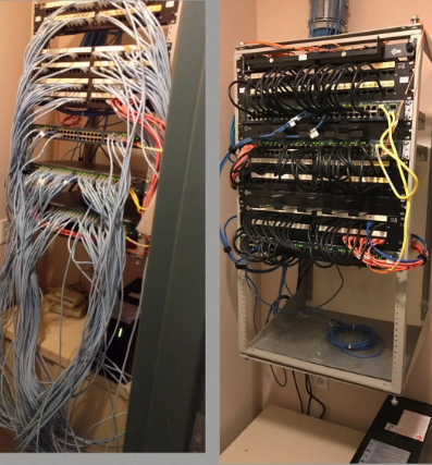
Wiring Closets
Wiring closets are essential for organizing network cables and devices.
- Patch panels serve as the connection points for cables coming from wall jacks.
- Houses networking equipment like switches, routers, and servers for easy access.
Fiber Optic Cables
Fiber optic cables are high-speed transmission media that use light to transmit data, offering greater bandwidth and distance capabilities than traditional copper cables. These cables are commonly used in backbone networks, long-distance communications, and high-speed data transfer.
- Transmit data as light signals through glass or plastic fibers.
- Immune to electromagnetic and radio frequency interference.
- Cover longer distances than copper cables.
- Provide higher bandwidth and faster transmission rates.
- Extremely resitant to eavesdropping and interference, but expensive.
Fiber Modes
-
Single Mode
-
Uses a single light path for data transmission.
-
Suitable for long-distance communication, up to hundreds of kilometers.
-
Typically used in telecom networks and large-scale data centers.

-
-
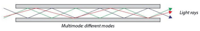
Multi-Mode
-
Multiple light paths transmit data simultaneously.
-
Effective for shorter distances, typically up to 2 kilometers.
-
Commonly used in local area networks (LANs) and within buildings.
-
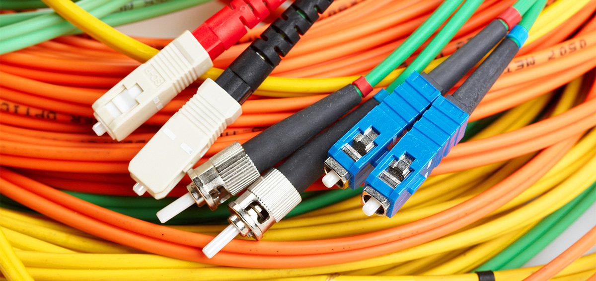
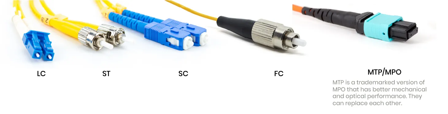
Fiber Connectors
-
Subscriber Connector (SC)
- Widely used in telecommunications and data networks.
- Push-pull coupling mechanism for easy connection and disconnection.
-
Lucent Connector (LC)
- Smaller footprint, allowing for higher density connections.
- Uses latch mechanism similar to RJ45 connectors for secure locking.
Network LAN Topologies
Network LAN topologies define the arrangement of devices and how they connect to each other. Understanding these configurations helps in optimizing performance and troubleshooting issues.
-
Bus Topology
- All devices share a single communication line or cable.
- Simple to set up but can lead to network failure if main cable fails.
-
Ring Topology
- Each device is connected in a circular fashion.
- Data travels in one direction.
- Failure in one device can disrupt the entire network.
-
Star Topology
- All devices connect to a central hub or switch.
- Offers high reliability.
- Failure of one device doesn’t affect others.
-
Tree Topology
- Combines characteristics of star and bus topologies.
- Hierarchical structure allows for easy expansion
- Can become complex to manage
-
Mesh Topology
- Each device connects to multiple other devices.
- Provides high redundancy and reliability
- Can be costly to implement due to cable requirements.