Networking Models
Overview
Networking models and standards define how hardware and software systems communicate and share information. Key goals include:
- Reliable Communication - Ensure data is sent and received correctly.
- Layered Functions - Separate responsibilities into layers for easier management.
- Packet-Based Transmission - Use packets as the basic unit of communication.
- Standardized Protocols - Consistent routing, addressing, and control mechanisms.
- Layer Extensibility - Allow additional functionality without disrupting core layers.
- Vendor-Neutral and Scalable - Work across different vendors and scale efficiently.
Layers
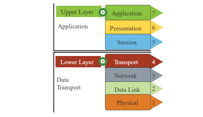
Most network models have at least two layers:
-
Upper Layer (Host/Application Layer)
- Handles connection integrity and session management.
- Transforms data into a universal format.
- Facilitates application-level communication.
-
Lower Layer (Media/Transport Layer)
- Receives bits from the physical medium
- Converts the received bits into frames.
- Adds routing information to create packets.
- Prepares data for higher layers to process.
OSI Model
The Open Systems Interconnection (OSI) Model is a conceptual framework for describing the communication structure of interconnected computer systems, comprising seven layers.
-
Application, Presentation, Session (Layers 5-7)
- Handle data formatting and session management
- Enable applications to talk across different systems
- Example: SNMP (Layer 7)
-
Transport Layer (4)
- Uses TCP/UDP protocols for reliable/connectionless delivery
- Ensures data is delivered in order and without errors
-
Network Layer (3)
- Handles routing and packet transmission
- Determines logical addressing and path selection
- Example protocols: IP, ICMP, IGMP
-
Data Link Layer (2)
- Manages frames and error detection/correction
- Controls access to physical medium and devices like switches
-
Physical Layer (1)
- Converts data into electrical, optical, or radio signals
- Hardware standards like cables, connectors, and signaling
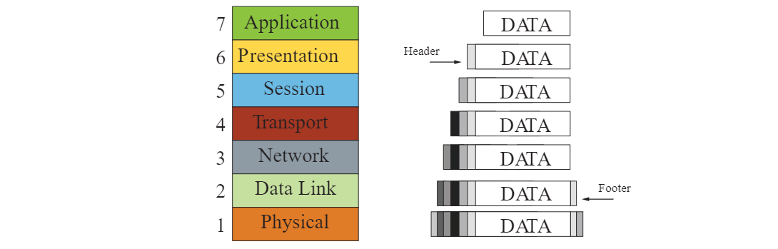
Encapsulation and De-encapsulation
When data is transmitted over a network, it goes through a process of encapsulation and de-encapsulation:
-
Encapsulation
- Data is wrapped with protocol information as it moves down the layers
- Each layer adds its own header (and sometimes footer)
- Headers/footers are used for routing, error checking, and delivery
- Prepares the data for transmission over the physical medium
-
De-encapsulation
- Data is unpacked as it moves up the layers
- Each layer removes its corresponding header/footer
- Information is processed after header/footer removal
- Original data is correctly delivered to receiving application
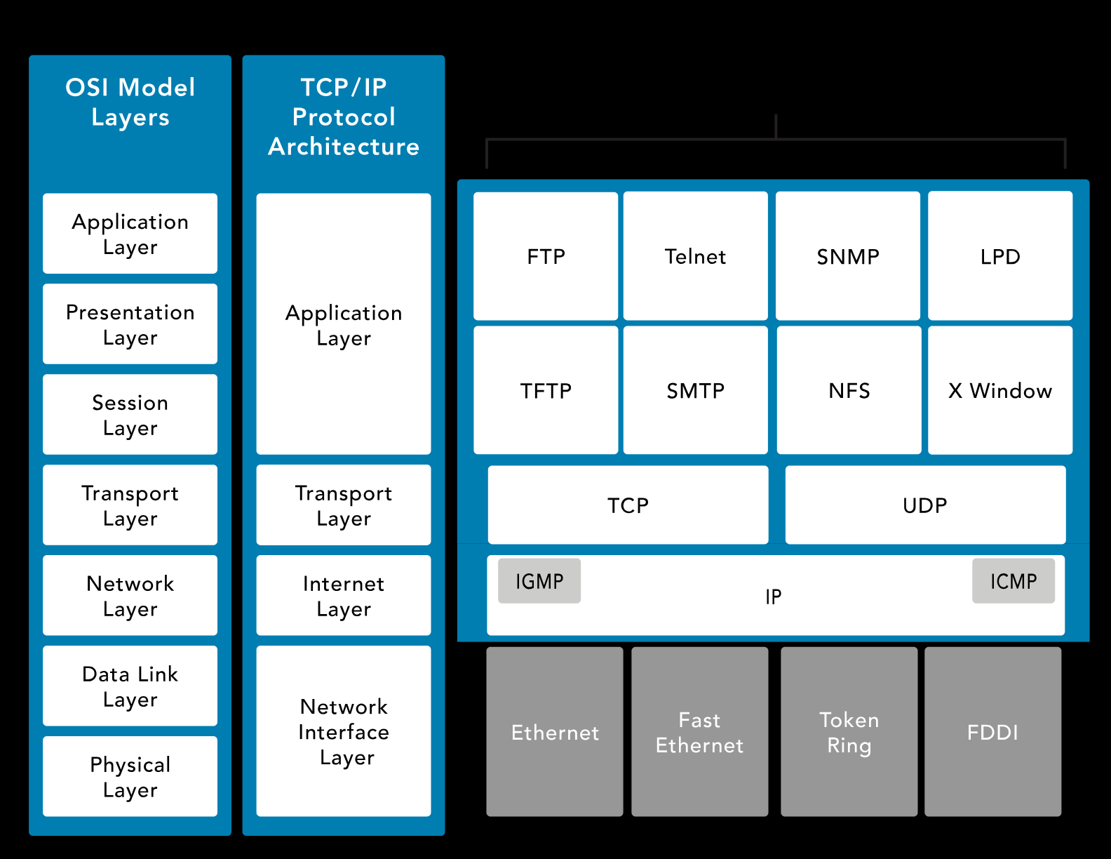
TCP/IP
Transmission Control Protocol/Internet Protocol (TCP/IP) is platform-independent but resource-intensive. It is designed for ease of use rather than security. It predates the OSI model.
-
Application Layer
- Defines transport layer protocol
- Example: Telnet, FTP, SMTP, DNS
-
Transport Layer
- TCP: Connection-oriented, reliable, full-duplex.
- UDP: Connectionless, fast, supports broadcast/multicast.
-
Internet Layer
-
Handles packets and routing.
-
ICMP: Ping and network health checks.
-
-
Network Interface Layer
- Manages data flow on physical networks
- Handles framing and error detection for data
- Controls access to physical network (e.g., Ethernet, Wi-Fi)
Transmission Types
Networks can send data in several ways depending on the target:
- Unicast: One-to-one communication between a sender and a single receiver.
- Broadcast: One-to-many communication to all devices on a network segment.
- Multicast: One-to-many communication to a specific group of devices.
- Anycast: One-to-one-of-many communication, delivered to the nearest or best receiver.
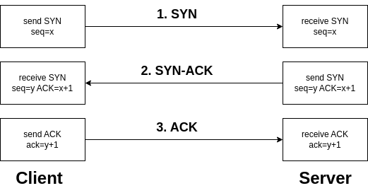
TCP Handshake
The SYN, SYN-ACK, and ACK handshake is a process used in the TCP (Transmission Control Protocol) to establish a connection between two devices on a network.
-
SYN (Synchronize)
- Initiates the connection request.
- The sender indicates its intention to establish a connection.
- The sender picks an initial sequence number.
-
SYN-ACK (Synchronize-Acknowledge)
- Acknowledges the receipt of the SYN packet.
- Indicates acceptance of the connection request.
- The receiver also selects an initial sequence number.
-
ACK (Acknowledge)
- Confirms the acknowledgment of the SYN packet.
- Establishes the connection.
- Data transfer can begin after the ACK is received.
This three-step handshake ensures that both the sender and receiver are ready to exchange data and have agreed upon initial sequence numbers for reliable communication.
UDP
User Datagram Protocol (UDP) is a connectionless protocol that enables fast data transmission without establishing a connection, which makes it suitable for low-latency applications like gaming and streaming.
- Connectionless, reducing overhead but less reliable
- No error checking or data recovery, leaving this to the application
- Lightweight, fast, and efficient for small data transmissions
- Supports broadcasting and multicasting
- Ideal for live broadcasts and conferencing
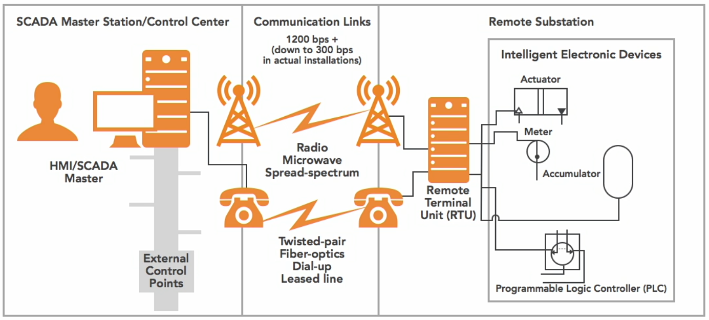
DNP3
Distributed Network Protocol (DNP3) is a multilayer communication protocol primarily used in utility and industrial automation systems to enable reliable and efficient data exchange between control equipment.
- Widely used in SCADA systems for real-0time monitoring and controll
- Robust communication, time-stamped data, and event logging
- Ensure interoperability between different vendors' equipment
How It Works:
- Remote Terminal Unit (RTU)
- The RTU gathers data from sensors or field devices
- Data is sent to the SCADA master station
- Communication Links
- Channels (wired or wireless) that facilitate the exchange of data
- Data is exchanged between RTUs and the SCADA master station.
- SCADA Master Station
- Central system that receives data from RTUs and processes it
- Issues control commands back to the RTUs
- Enables real-time monitoring and control of the entire network.
Diagram:
Network Types
Local Area Network (LAN)
A LAN is a network that connects devices within a small, localized area.
- Covers a small area like a home, office, or campus
- High-speed connectivity for local devices
- uses Ethernet or Wi-Fi for fast and reliable communication
- Typically owned and managed by a single organization
Metropolitan Area Network (MAN)
A MAN connects multiple LANs across a city or metropolitan area.
- Covers a city or metropolitan region
- Larger than a LAN but smaller than a WAN
- Used by service providers to connect businesses or campuses
- Provides higher-speed connectivity than WANs for urban areas
Metropolitan area network architectures are commonly built upon the following layers:
-
Access
- Connects customer devices to the provider’s network
- May include routers, switches, or optical interfaces
-
Aggregation/Distribution
- Collects and forwards traffic from the access layer
- Optimizes traffic flow and performs load balancing
-
Metro
- Intermediate layer, routes traffic across the metropolitan area
- Provides redundancy and high-capacity backbone connections
-
Core
- Routes traffic to destination aggregation network efficiently
- Connects to WAN or other MANs for long-distance communication
Wide Area Network (WAN)
A WAN connects networks across large geographic distances.
- Connects networks over cities, countries, or even continents
- Often uses leased lines, MPLS, VPNs, or satellite links
- Enterprise connectivity, remote office access, and internet backbones
- Managed by service providers rather than individual organizations
Circuit-Switched vs Packet-Switched
Circuit-switched is a communication method where a dedicated path is established for the entire session.
- Dedicated path for the duration of the session
- Ensures consistent bandwidth and low delay
- Used in traditional telephone networks
Packet-switched breaks data into packets and sent over shared network paths.
- More efficient use of bandwidth, but has variable delay
- Common in modern IP networks and the Internet
Multiplexing Techniques
Multiplexing is a method of combining multiple signals to share a single communication channel efficiently.
-
Time-Division Multiplexing (TDM)
- Multiple signals share a channel by taking turns in fixed time slots
- Ensures predictable timing and low interference
- Common in digital telephony
-
Statistical Time-Division Multiplexing (STDM)
- Dynamically allocates time slots based on active demand
- More efficient than fixed TDM when traffic is bursty
- Reduces wasted bandwidth
-
Frequency-Division Multiplexing (FDM)
- Each signal occupies a separate frequency band simultaneously
- Common in analog radio and TV transmission
- Requires filters to avoid overlap between bands
-
Wavelength-Division Multiplexing (WDM)
- Optical fiber variant of FDM using multiple light wavelengths
- Increases fiber capacity without laying more cables
- Used in long-distance and high-speed networks
Bit Rate Categories
Bit rate categories define how much data is transmitted per unit time and the guarantees provided by the network.
-
CBR (Constant Bit Rate)
- Connection-oriented, fixed throughput
- Suitable for voice/video applications that need consistent delivery
- Predictable performance with low latency
-
UBR (Unspecified Bit Rate)
- Connectionless, no guaranteed throughput
- Best for non-critical applications like file transfers
- No reserved bandwidth, may experience variable delay
-
VBR (Variable Bit Rate)
- Connection-oriented, throughput varies depending on traffic
- Balances efficiency and service quality
- Good for applications tolerant to delays
- Example uses: Email or web browsing
-
ABR (Available Bit Rate)
- Connection-oriented
- Dynamically adjusts throughput based on network load
- Ensures fair bandwidth allocation among users
- Useful in shared networks where traffic fluctuates
Session Layer Communication Modes
The session layer defines how two applications communicate over a network.
-
Simplex
- Communication flows in one direction only
- Rare in practice; mostly used for broadcasting or sensors
-
Half-Duplex
- Two-way communication, but only one side sends at a time
- Example: walkie-talkies
-
Full-Duplex
- Two-way communication simultaneously
- Example: telephone conversations, Ethernet networks
SNMP
Simple Network Management Protocol (SNMP) is used to monitor and manage network devices.
- Tracks device status, performance, and alerts
- Consists of a manager (central server) and agents (network devices)
- Enables network administrators to maintain health, configure devices, and respond to issues