Routing and Network Diagrams
Overview
Routing moves packets between networks, and network diagrams document how those networks are connected. Together, they make troubleshooting and design easier.
Routers and Routing
Routers operate at Layer 3 of the OSI model and the internet layer of the TCP/IP model. They forward packets between networks based on routing table entries.
A router performs two main tasks:
- Path determination: Select the best route to the destination network.
- Packet forwarding: Send the packet out the correct interface or to the next hop.
Routing Table Entries
A routing table lists known destination networks and how to reach them.
| Network | Interface or Next Hop |
|---|---|
| 10.9.2.0/24 | Directly connected: Gi0/0 |
| 10.9.1.0/24 | Directly connected: Gi0/1 |
| 10.5.3.0/24 | Directly connected: Se0/0/1 |
| 10.8.3.0/24 | Via 10.9.2.2 |
Common route types:
| Type | Description |
|---|---|
| Directly connected | Added when an active interface has an IP address. |
| Static | Manually configured by an administrator. |
| Dynamic | Learned from routing protocols such as OSPF, EIGRP, or BGP. |
| Default | Used when no more specific route matches the destination. |
Router Planes
Router behavior is often described through three planes.
| Plane | Purpose |
|---|---|
| Management | Handles traffic destined to the device itself, such as SSH. |
| Control | Builds network knowledge through routing protocols and logic. |
| Data | Forwards packets using information from the control plane. |

Packet Forwarding
Cisco routers support several forwarding mechanisms:
| Mechanism | Description |
|---|---|
| Process switching | CPU checks the routing table for each packet. |
| Fast switching | CPU handles the first packet and caches next-hop information. |
| CEF | Uses a Forwarding Information Base and adjacency table. |
Cisco Express Forwarding is the default and fastest mechanism on modern Cisco routers and multilayer switches.
Network Diagrams
Network diagrams document the network so engineers can understand design, connectivity, and troubleshooting scope.
Two common diagram types are:
| Diagram Type | Purpose |
|---|---|
| Layer 2 | Shows physical connectivity, switch ports, and cabling paths. |
| Layer 3 | Shows IP networks, router links, and routing relationships. |
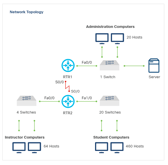
Interface Naming
Cisco interface names commonly include the module and port number.
Examples:
| Interface | Meaning |
|---|---|
| FastEthernet 0/0 | First port on the first FastEthernet module. |
| FastEthernet 0/1 | Second port on the first FastEthernet module. |
| FastEthernet 1/2 | Third port on the second FastEthernet module. |
Network diagrams should include interface names when they help map logical topology to physical devices.