TPU Runtime and Interoperability
Overview
Runtime selection and accelerator portability affect both delivery speed and model performance. This page covers TPU software versions and practical strategies for switching between TPU and GPU paths.
TPU Software Version
When you create TPU resources, you choose a TPU software version, which is also called a runtime version. This version defines the pre-installed software environment on the TPU VM.
This environment includes:
- The underlying Ubuntu operating system
- Docker (for containerization)
- Other required runtime components for TPU workloads
You can select the software version in two ways:
-
Google Cloud CLI
Use the
--versionflag, or--runtime-versionwhere supported.gcloud compute tpus tpu-vm create lab-tpu --zone ${ZONE} \--accelerator-type=v6e-4 \--version v2-alpha-tpuv6e -
Google Cloud console
Select from the TPU software version list.
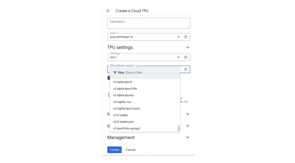
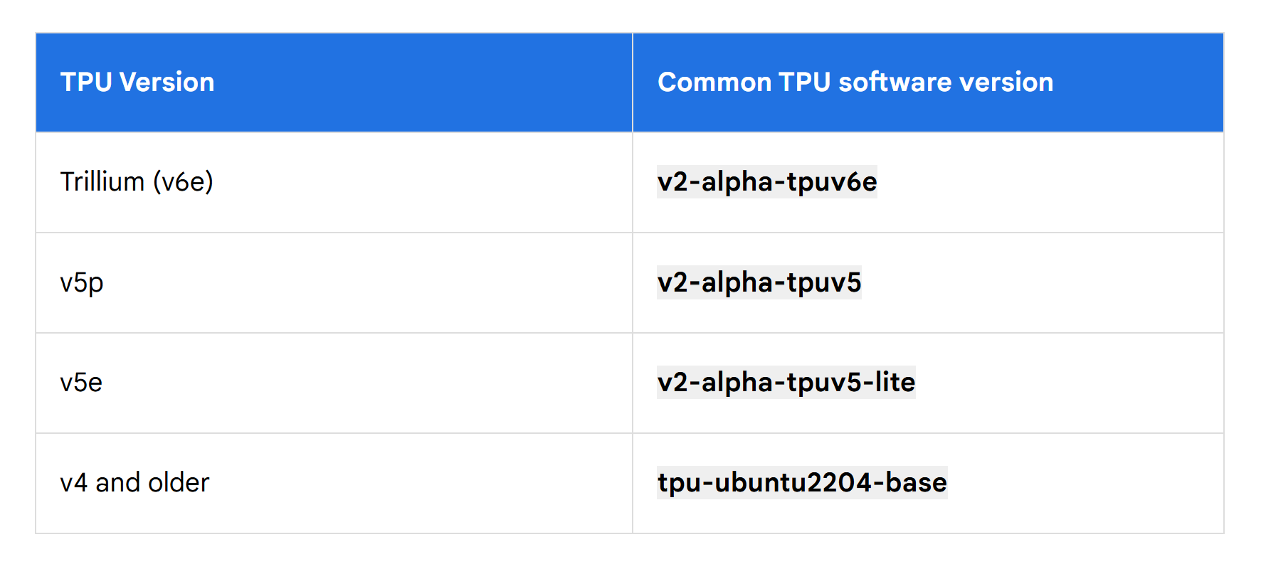
For PyTorch or JAX, runtime selection is simple. You pick a base version that supports your TPU hardware, and then install your framework on top.
The table below shows common TPU software versions by TPU hardware generation:
Note: Runtime mismatches can block launches or degrade performance, so validate runtime and framework compatibility before provisioning large slices.
Interoperability Between TPU and GPU
LLM deployment usually involves tradeoffs between cost, performance, and capacity.
TPU and GPU interoperability lets one deployment use both accelerator types. You can prioritize performance when needed and shift to lower-cost capacity when available.
Before implementing that pattern, first choose the best default hardware path for your model. The decision trees below provide a simple way to make that choice.
1. Start from TPU-optimized code
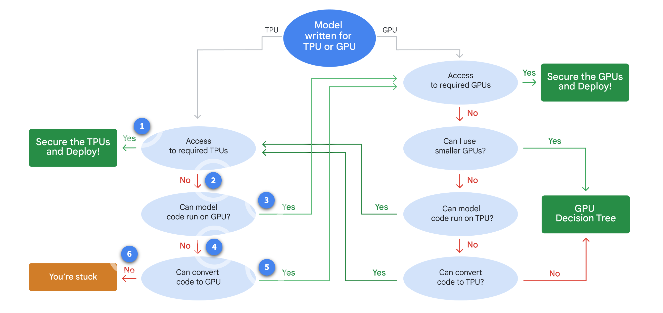
Use this path when your model code is already TPU-optimized and TPU performance is the priority.
Notes:
-
Start with a TPU-first model and check TPU capacity.
- Do you have access to the required TPUs?
- If yes, you can secure the TPUs and deploy. You've found your match.
-
If TPU capacity is unavailable, check whether the model can run on GPU.
- Many frameworks support both, so this is often possible.
-
If it can run on GPU, verify GPU capacity.
- Check if you have access to the required GPUs.
-
If it cannot run on GPU, your model strictly needs a TPU or significant changes.
- Estimate the effort to convert the model.
-
If conversion is feasible, continue with GPU capacity planning.
-
If conversion is not feasible and TPU capacity is unavailable, you're stuck.
- Revisit the model or resource strategy.
2. Start from GPU-optimized code
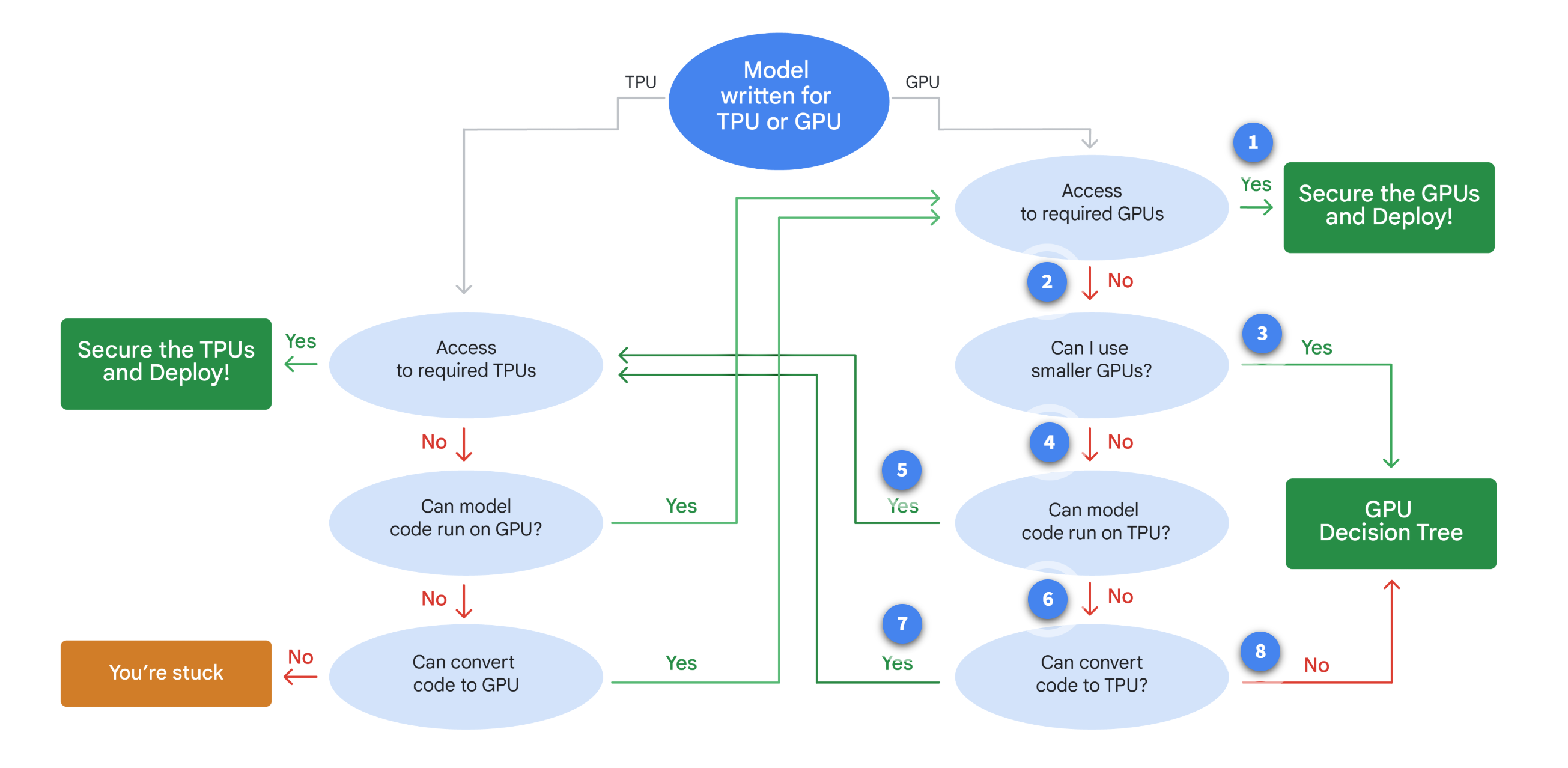
Use this path when your model is GPU-optimized and GPU is the default runtime target.
Notes:
-
Start with a GPU-first model and check GPU capacity.
- Do you have access to the required GPUs?
- If yes, secure the GPUs and deploy. This is the most direct route.
-
If GPU capacity is unavailable, can you use smaller GPUs?
- Sometimes, less powerful GPUs can work for your workload.
-
If smaller GPUs are viable, secure that capacity and deploy.
-
If smaller GPUs are not viable, check whether the model can run on TPU.
- This is a key flexibility point.
-
If it can run on TPU, verify TPU capacity.
- This decision loops you to the TPU access question.
-
If it cannot run on TPU, your model is firmly GPU-bound.
- Estimate the effort to convert the model.
-
If conversion is feasible, continue with TPU capacity planning.
-
If conversion is not feasible and GPU capacity is unavailable, you're stuck.
- Revisit the model or resource strategy.
Switching with vLLM on GKE
This pattern lets one GKE deployment serve on both TPU and GPU while keeping scheduling behavior predictable.
Core setup:
- A custom compute class sets node pool priority.
- TPU nodes are the primary target for performance.
- GPU nodes are the fallback for availability and cost control.
- Each pod runs two vLLM containers, one for TPU and one for GPU images.
- Container matching the node accelerator starts, the other stays idle.
With this setup, scaling flow is simple:
- Initial traffic lands on TPU nodes when capacity is available.
- When TPU capacity is full, new pods are scheduled to GPU nodes.
For example, if the TPU pool is limited to one node, later pods move to L4 GPU pools. This ensures that the workload continues to run even when TPU capacity is constrained.
Tradeoffs
There is a tradeoff between cross-hardware interoperability and peak performance from hardware-specific optimization.
| Area | Practical Impact |
|---|---|
| Interoperability | One deployment can run across TPU and GPU pools. |
| Peak hardware efficiency | Lower than fully hardware-specific optimization in some workloads. |
| Portability effort | XLA-based paths can still require code changes in some serving stacks. |
| vLLM on TPU | Backend handles key TPU interoperability work used in this module's demo. |
Note: Other serving libraries may require more manual changes for TPU and GPU portability.