TPU System Architecture
Overview
At the hardware level, each Cloud TPU chip combines specialized processing units for tensor operations.
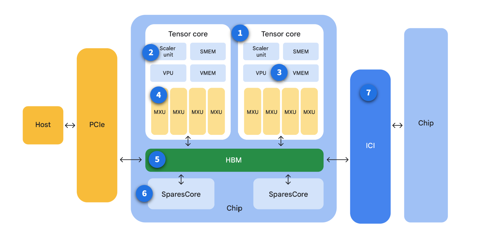
Older TPUs (before Trillium) used 128x128 arrays, while Trillium uses larger 256x256 arrays.
Each MXU can perform up to 16,000 multiply-accumulate operations per cycle.
TPUs use bfloat16 for multiplication, and FP32 for accumulation. This helps balance speed and numerical accuracy.
Architecture
TensorCore
TensorCore is the primary compute engine in a TPU chip.
- Handles most tensor and matrix acceleration work.
- Appears one or more times per chip.
- Varies by TPU generation, such as v3, v4, v5e, and v5p.
TensorCore provides most of the chip-level acceleration you rely on for model compute.
Scalar unit
The scalar unit manages control and coordination tasks.
- Handles control flow logic.
- Computes memory addresses.
- Runs housekeeping operations needed by other units.
The scalar unit keeps TPU execution organized and predictable.
Vector unit
The vector unit handles non-matrix math in the TPU pipeline.
- Includes the Vector Processing Unit (VPU).
- Uses Vector Memory (VMEM) for vector operations.
- Runs operations like activation functions and softmax.
This unit complements MXUs by handling general vector-heavy computation.
Matrix-multiply units (MXUs)
MXUs are the core matrix engines that provide most of TPU throughput.
- Implemented as systolic arrays of multiply-accumulators.
- Connect many compute cells in a matrix layout.
- Optimize multiply-accumulate operations used in deep learning.
When you run large models, MXU efficiency strongly influences overall performance.
High Bandwidth Memory (HBM)
HBM provides high-speed memory access for TPU workloads.
- Feeds data quickly to compute units.
- Reduces memory bottlenecks during training and inference.
- Supports large tensor movement at high bandwidth.
HBM helps TPU cores stay utilized instead of waiting on memory.
BarnaCore/SparseCore
SparseCore is designed for sparse and embedding-heavy workloads.
- Accelerates sparse dataflow operations.
- Improves performance for embedding-centric models.
- Commonly helps recommendation-style workloads.
TPUs include SparseCores so sparse operations do not become a performance bottleneck.
- TPU v5p chips feature four SparseCores per chip.
- Trillium TPU chips include two SparseCores per chip.
The exact SparseCore count depends on TPU generation.
Inter-chip-interconnect (ICI)
ICI is Google's high-speed interconnect between TPU chips.
- Connects chips for distributed execution.
- Supports low-latency data exchange.
- Enables scale-out training across many chips.
ICI is a key reason TPU pods can train large models efficiently at scale.
Scaling From Chips To Pods And Slices
TPU scaling combines physical packaging and logical allocation.
TPU Cube
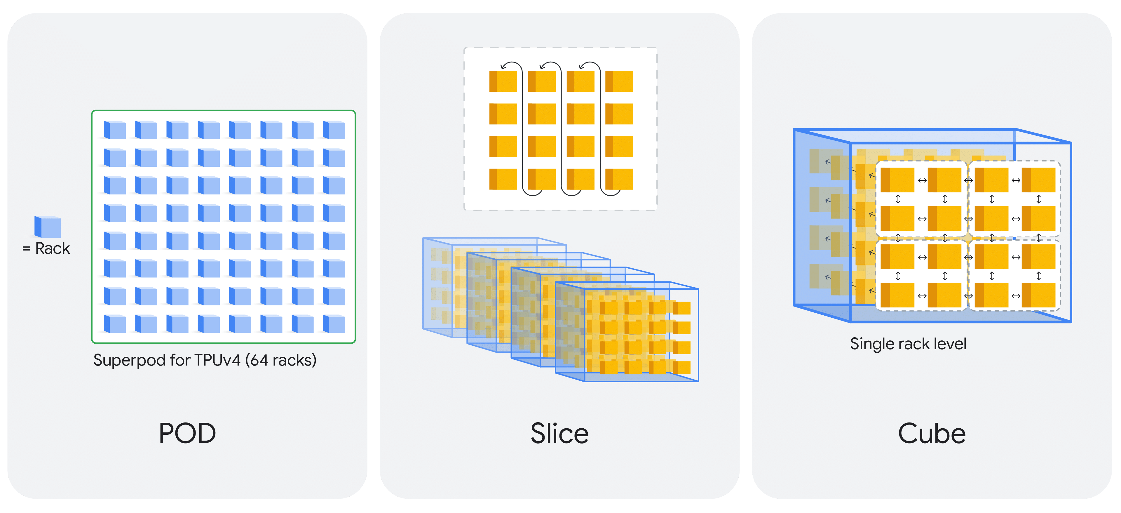
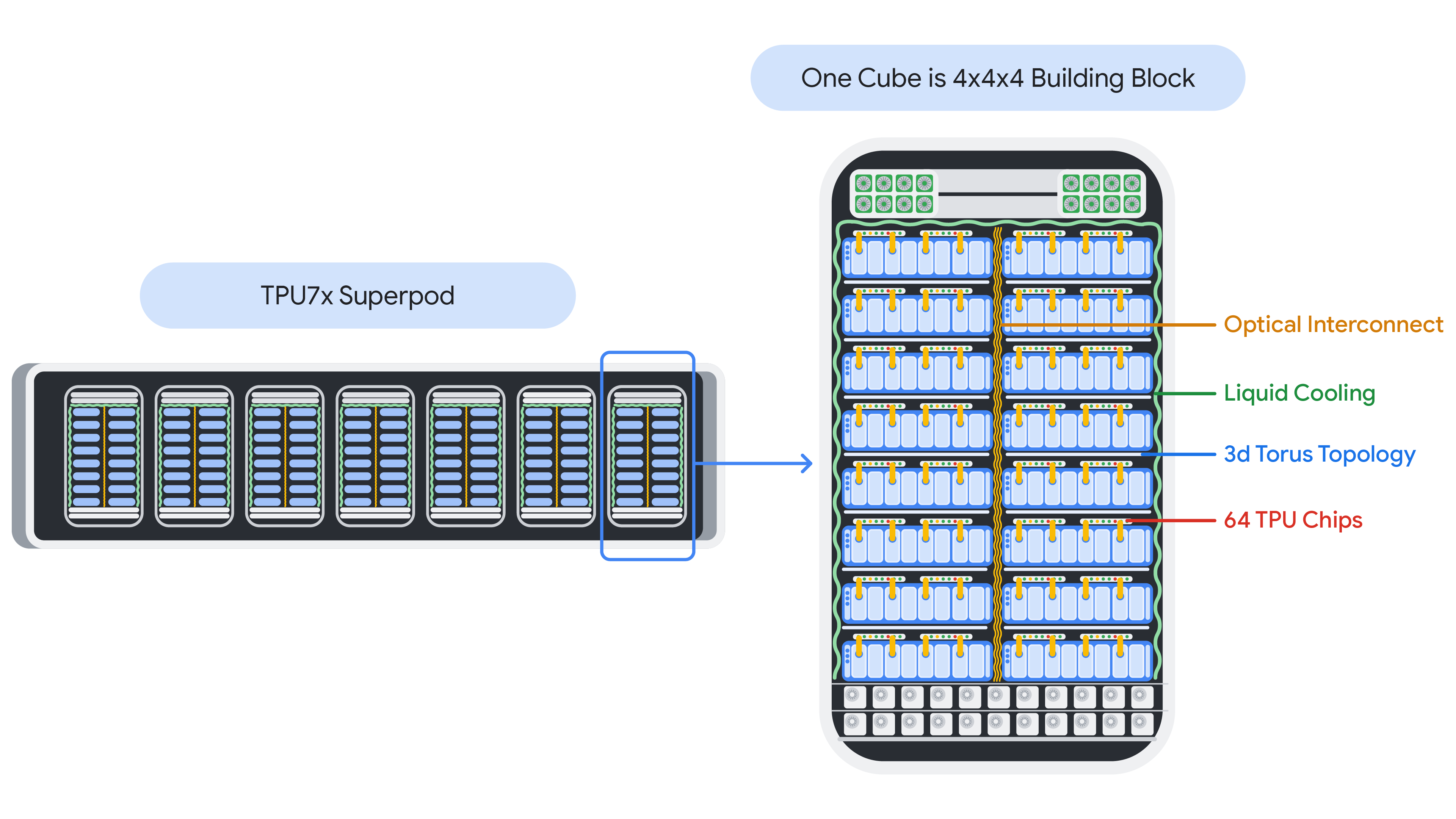
A cube is a physical unit that contains 64 chips. It is a 4x4x4 topology of interconnected TPU chips. This is only applicable to 3D topologies (beginning with TPU v4). They are also known as a "rack".
TPU Pod
A TPU pod is a collection of TPUs that are physically grouped together and connected by a specialized, high-speed network. The total number of TPU chips within a pod varies by TPU version.
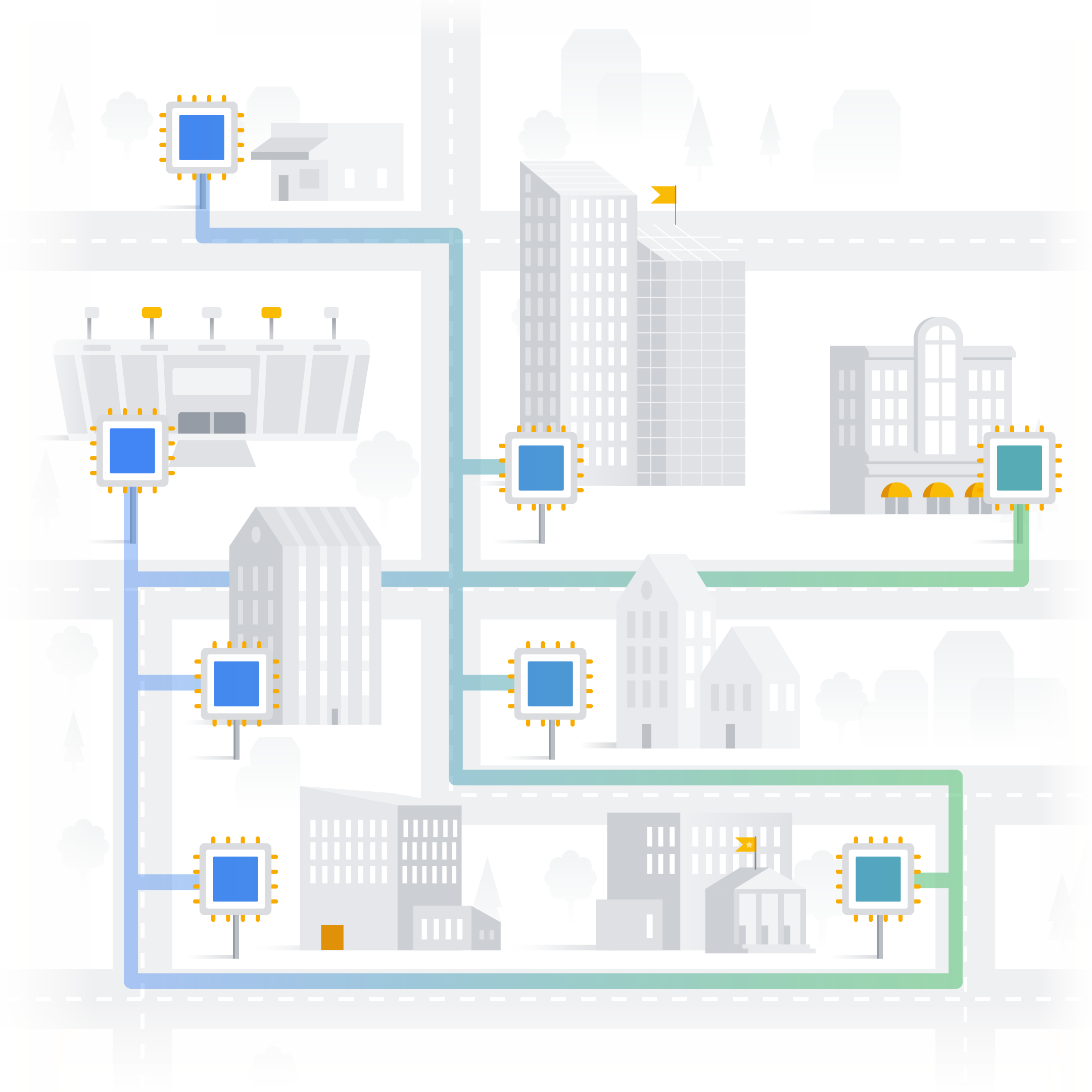
City analogy: A TPU pod is like a dedicated, super-fast neighborhood within that city, designed specifically for AI compute.

Slice
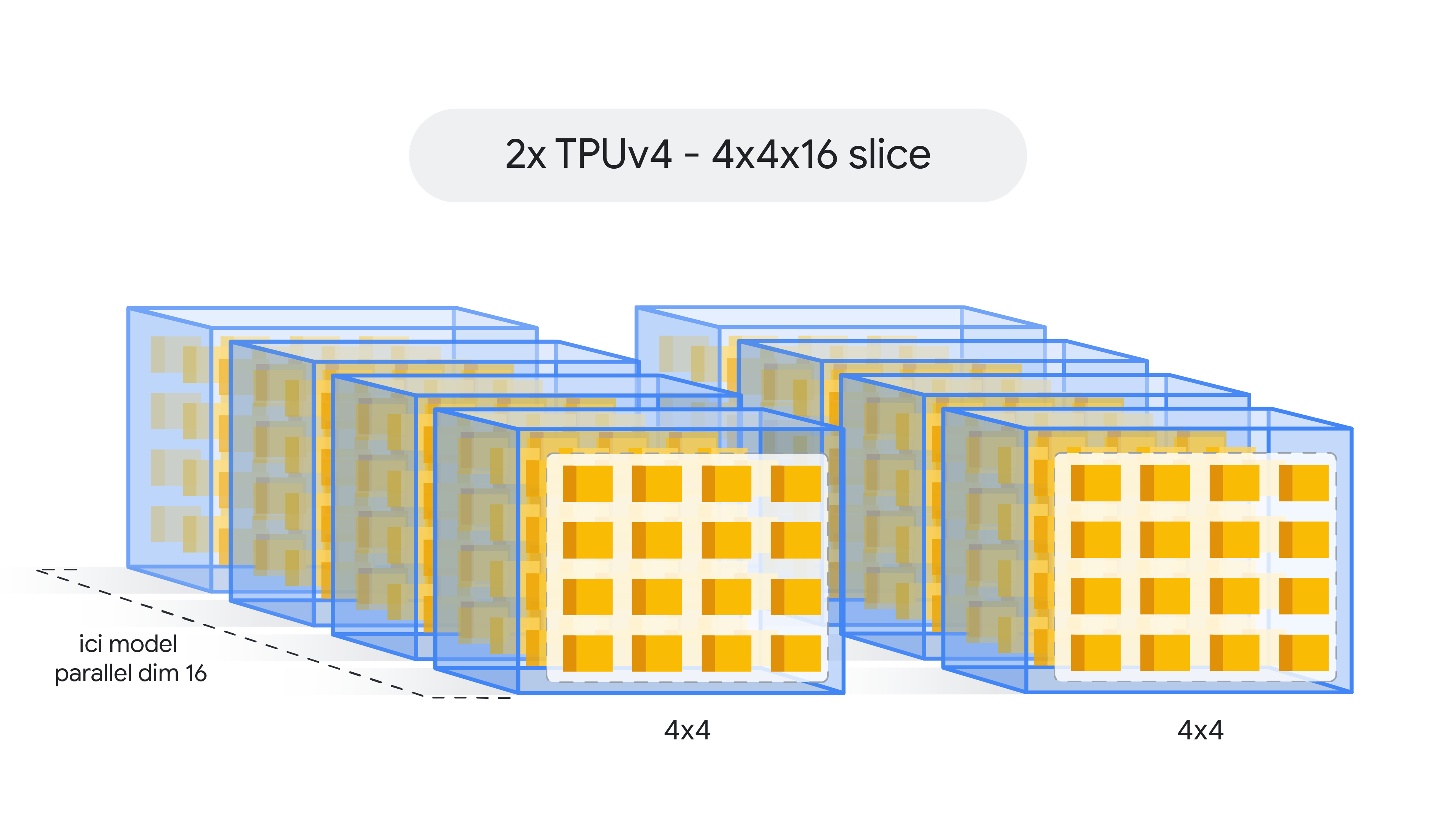
A slice is a logical subset of chips within one pod. They can start small and scale up to superpod-sized allocations.
- Chips in a slice communicate over high-speed ICI links.
- Slices are described by chip count, TensorCore count, and topology shape.
TPU rack vs. TPU slice: The key difference is that a TPU slice is a flexible logical unit, while a TPU rack or pod is a fixed physical unit. Physical layout still matters, but this section focuses on the conceptual view.
Slice shape and chip topology describe how chips are arranged and interconnected for your workload.
City analogy: A TPU slice is like a specific block or district within the neighborhood (TPU pod) where information (data) can flow quickly between buildings (TPU chips).
Multislice
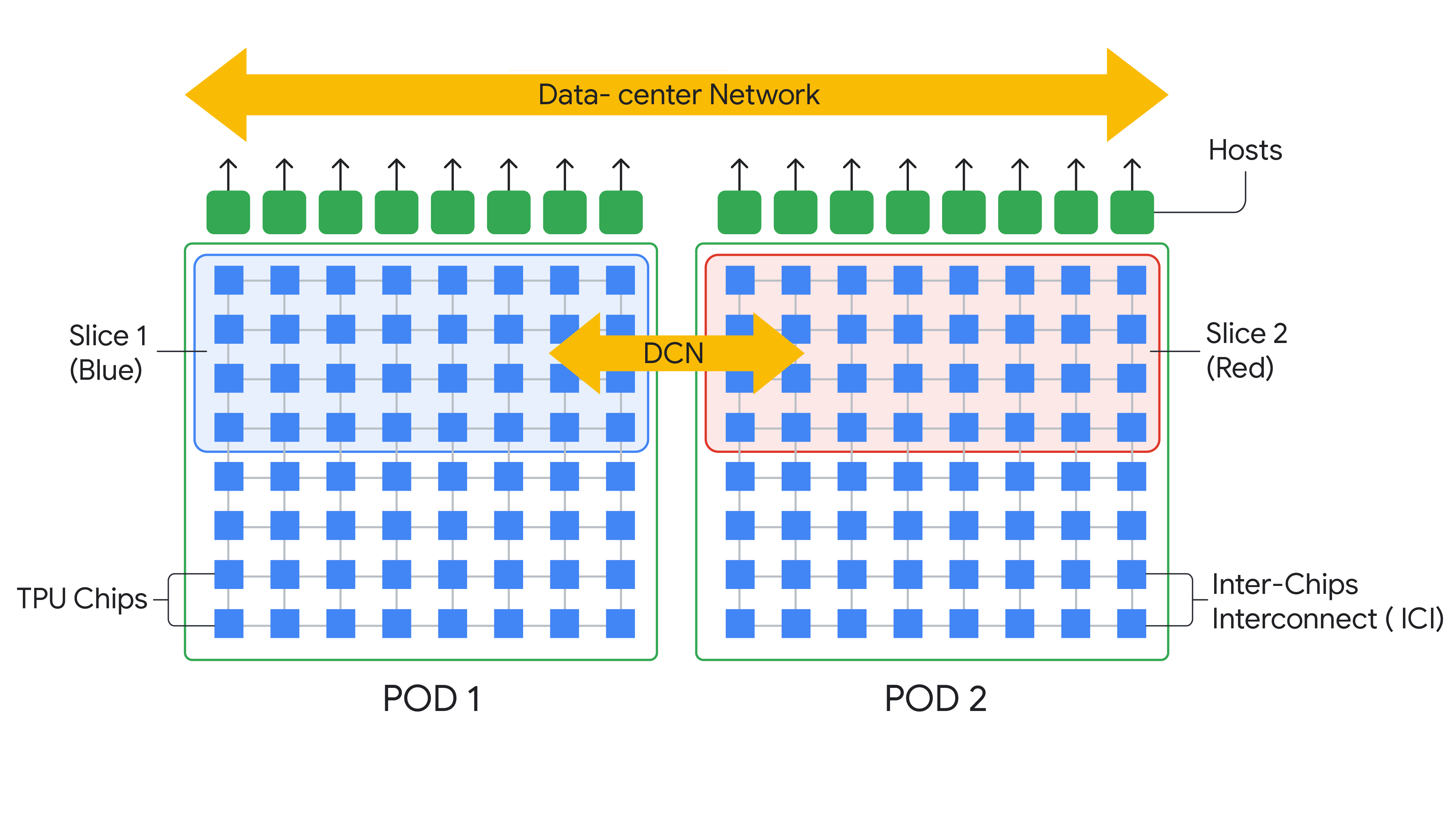
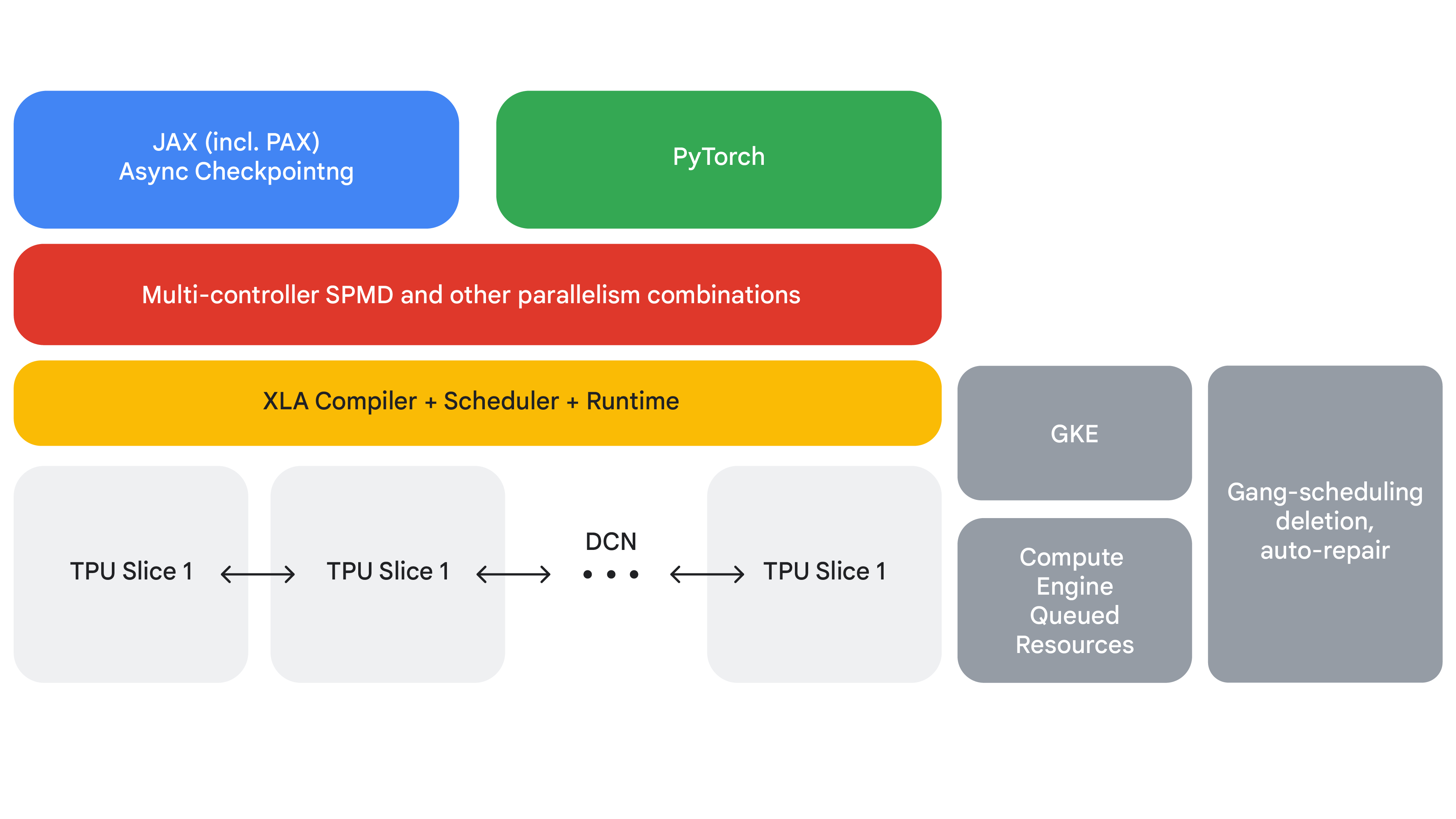
When one slice is not enough, Multislice extends distributed training across multiple slices by combining ICI within slices and DCN between slices.
How Multislice Works
Multislice uses two network layers so jobs can scale beyond a single slice boundary.
- Intra-slice traffic uses ICI.
- Inter-slice traffic uses DCN.
- Runtime, scheduler, frameworks, and orchestration coordinate full-stack execution.
The diagram below shows how this model extends across larger distributed layouts.
Benefits of Multislice
Multislice adds scale while keeping operations practical for large training jobs.
- Massive scalability for very large model training.
- Near-linear performance scaling in many distributed scenarios.
- Better developer productivity with simpler scaling patterns.
- Improved cost efficiency through better utilization.
- Higher robustness with repair and recovery features.
In short, multislice training gives you the infrastructure and optimizations needed to train LLMs that are too large for a single device, with better efficiency, cost control, and developer productivity.
ICI Resiliency
ICI resiliency improves reliability of optical ICI links and optical circuit switch paths.
- Enables rerouting around some optical faults.
- Improves scheduling availability for larger slices.
- Can introduce minor temporary performance impact during reroute.
For Cloud TPU v4 and v5p, this is enabled by default for slices that are one cube or larger (e.g., v5p-128 or 4x4x4 configurations).